Pickett N-515-T CIE Electronic · Volume 3
Pickett N-515-T Electronic (CIE) — Volume 3 — The Back Face: The Decimal Point Locator and the Formula Panels
How Darrell Geiger's patented scales put the decimal point in the right place, and everything printed beside them
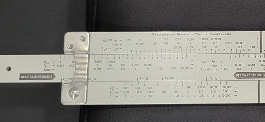

Figure 1 — The back of my N-515-T. Left half: the “Reactance and Resonance Decimal Point Locator,” with “REACTANCE PROBLEMS” and “RESONANCE PROBLEMS” sections on the slide. Right half: formula panels for temperature, impedance, transformers, Ohm’s law (DC and AC), frequency and wavelength, reactance, resonance, decibels, power factor, parallel resistors, coupled inductance and efficiency; a table of constants; the CIE seal; and “CLEVELAND INSTITUTE OF ELECTRONICS, CLEVELAND, OHIO 44114, PATENT NO. 3,120,342, MADE IN U.S.A.” Photo: my own.
3.1 About This Volume
Turn the N-515-T over and it stops looking like a slide rule. There are no logarithmic cycles marked 1 to 10, no trigonometric scales — only rows of decimal numbers such as 0.001, 0.01, 0.1, 1, 10, 100, small arrows, unit symbols, and two boxed legends, Reactance Problems and Resonance Problems. This is the Reactance and Resonance Decimal Point Locator of US Patent 3,120,342, the reason the rule exists. The rest of the back is a printed reference card of the formulas a radio technician needed most. This volume explains the locator — what each row means, why the scales are spaced the way they are, and how to use it — and transcribes the formula panels.
3.2 The Problem the Locator Solves
Every reactance and resonance problem has the same awkward shape. The three formulas the patent singles out are
XL = 2πfL XC = 1 / (2πfC) f = 1 / (2π√(LC))
each with three quantities, so nine possible problems — find XL given f and L, find L given XL and f, and so on. In practice the quantities come in mixed units: capacitance in microfarads or picofarads, inductance in henrys, millihenrys or microhenrys, frequency in hertz, kilohertz or megahertz, reactance in ohms or megohms. To use the formulas as written, everything has to be converted to farads, henrys and hertz first — numbers like 3.5 × 10⁻⁴ and 2 × 10⁵ — and converted back afterwards.
The front face of the rule gives the digits of the answer to three figures, but not the decimal point. Geiger’s patent sets two objects for the back face: that problems “can be readily solved without need for conversion from one unit of measure to another,” and that “an accurate determination of the correct decimal point location is obtainable immediately and directly.” The answer is a second, deliberately crude slide rule whose scales are marked in practical units and whose only job is the order of magnitude.
3.3 How the Locator Is Built
Figure 2 — The locator on my rule. Upper body: three rows labelled CµF or LH, LmH, and CpF or LµH. Slide, “Reactance Problems” section: rows fHz, fkHz, fMHz, and four arrow marks along the slide’s lower edge — XC MΩ, XL Ω, XC Ω, XL MΩ. Lower body: rows XC, XL and f. The slide continues to the right into the “Resonance Problems” section (Figure 1). Photo: my own.
3.3.1 Coarse logarithmic scales
Each of the locator’s scales is a row of equally spaced main marks, one decade apart: 0.001, 0.01, 0.1, 1, 10, 100 and so on. Between each pair of main marks are two intermediate marks labelled 2 and 5. The patent specifies their spacing precisely: they divide each decade into three spaces “whose lengths relative to each other are represented by the integers 3, 4 and 3.”
That ratio is not arbitrary. On a logarithmic scale the distance from 1 to 2 is log 2 = 0.301 of a decade, from 2 to 5 is log 2.5 = 0.398, and from 5 to 10 is log 2 = 0.301 — almost exactly 3 : 4 : 3. The locator is therefore a real logarithmic slide rule, but with one decade per division and only two subdivision marks: just enough resolution to tell 2 from 5, and nothing finer. A whole decade of the front face’s C scale — ten inches — is compressed into a little under half an inch of locator scale.
Because one length of scale stands for every unit, the same graduations can carry several rows of numbers for different units, each row offset by the right power of ten. That is how unit conversion is abolished: 1 µF and 1,000,000 pF are the same point on the scale, so they appear in the same column, in different rows.
3.3.2 The rows and their arrows
Table 1 — The rows and their arrows
| Where | Row label | Meaning | Direction of increase |
|---|---|---|---|
| Upper body | CµF or LH | capacitance in microfarads, or inductance in henrys | ← leftward |
| Upper body | LmH | inductance in millihenrys | ← leftward |
| Upper body | CpF or LµH | capacitance in picofarads, or inductance in microhenrys | ← leftward |
| Slide (reactance) | fHz, fkHz, fMHz | frequency | → rightward |
| Slide (resonance) | CµF or LH, LmH, CpF or LµH | the second of L or C | → rightward |
| Lower body | XC | capacitive reactance, ohms (or megohms, by arrow) | → rightward |
| Lower body | XL | inductive reactance | ← leftward |
| Lower body | f | resonant frequency | → rightward, one decade per two divisions |
Small arrows at the ends of each row point in the direction in which its values grow. The course explains why they are there: “Knowing the direction of progression of the scales makes it easier to set and read values.” The directions are chosen so that the right answer falls out of the geometry:
- On the upper body, values grow to the left, on the slide to the right. Setting a slide value opposite a body value therefore adds their logarithms in the slide’s displacement — the slide’s position encodes the product fC, fL or LC.
- XC = 1/(2πfC) falls as fC rises, XL = 2πfL rises as fL rises, so the XC and XL rows on the lower body run in opposite directions.
- Resonant frequency depends on the square root of LC, so a decade change in LC moves f by only half a decade. The f row on the lower body therefore has two divisions per decade, In the patent, the scale behind this row has a single intermediate mark midway between main marks, labelled 3 — standing for √10 ≈ 3.16, the halfway point of a decade on a logarithmic scale — and the frequency row carries small secondary figures 2, 3 and 6 within each decade.
3.3.3 The arrow marks
The answer is not read at a hairline but opposite an arrow mark printed on the slide’s lower edge, pointing down at the lower body. There are two groups:
- Reactance Problems: four arrows, labelled XC Ω, XC MΩ, XL Ω and XL MΩ, for reading a reactance in ohms or megohms.
- Resonance Problems: arrows labelled fHz, fkHz and fMHz, for reading a resonant frequency in the unit wanted.
Each arrow is displaced from the decade marks by the amount needed to absorb the constant factor in its formula — the 2π in the reactance formulas, the 2π and the square root in the resonance formula — together with the unit change from ohms to megohms or hertz to megahertz. The patent states the positions: the reactance arrows stand “at 0.159 of the length of the main scale spaces,” the resonance arrows at 0.318. (Those numbers are the values of 1/2π and 1/π.) On the patent drawing the lowest-unit resonance arrow falls beyond the end of the printed f row, and the patent says so: the row’s numbers were simply not extended that far.
3.4 Using the Locator
The course gives one rule for each type of problem (Part III, Topics 26 and 27).
Resonance: “Set the value of either C or L (it makes no difference which one) on the Resonance Problems Scale of the slide opposite the other given value on the upper body scale. Then read the approximate frequency on the bottom body scale opposite the appropriate arrow on the slide.”
Reactance: “The frequency on the part of the slide marked ‘Reactance Problems’ is placed opposite the given value of inductance or capacity on the upper body of the rule. The reactance is then read on the proper scale on the lower body opposite the appropriate arrow of the slide.”
Run backwards, the same settings find a missing L, C or f. The course is equally clear about the precision required: “A high degree of accuracy is never necessary in setting values on the Decimal Point Locator scales.”
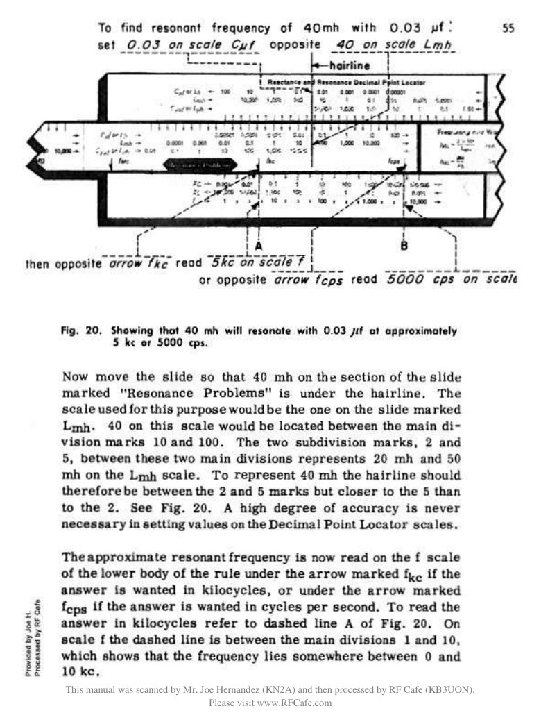
Figure 3 — Part III, page 55: “To find resonant frequency of 40 mh with 0.03 µf: set 0.03 on scale Cµf opposite 40 on scale Lmh; then opposite arrow fkc read 5 kc on scale f, or opposite arrow fcps read 5000 cps.” Image: Cleveland Institute of Electronics, Electronics and Your Slide Rule, Part III, scanned by Joe Hernandez (KN2A), via RF Cafe, https://www.rfcafe.com/references/electrical/Cleveland-Institute-515-T-Slide-Rule-Manuals.htm.
3.4.1 Worked examples from the course, checked
Each of the following is a worked example in Part III. The “exact” figure was computed directly from the formula for this unit; the locator figure is the course’s own.
Resonance (Example in Topic 26) — 40 mH in parallel with 0.03 µF. On my rule’s labelling: set the hairline over 0.03 on the CµF row of the upper body (between the 0.01 and 0.1 main marks, nearer the 2 than the 5); move the slide until 40 on its LmH resonance row (between 10 and 100, nearer the 5) is under the hairline; read the f row opposite the fkHz arrow. The arrow falls between the 3 and 6 marks of the decade 1–10, nearer 6: about 5 kHz. Exact: f = 1 / (2π√(0.040 × 0.03 × 10⁻⁶)) = 4,594 Hz. The locator’s job is done: the answer is a few kilohertz, not a few hundred hertz or tens of kilohertz.
Capacitance for resonance (Example 31) — What capacitance resonates with 350 µH at 200 kHz? Set the fkHz arrow opposite 200 on the f row; set the hairline over 350 on the LµH row of the upper body; read under the hairline on the slide’s CµF row: about 0.003 µF. Exact: C = 1 / ((2π × 200,000)² × 350 × 10⁻⁶) = 1.809 × 10⁻⁹ F = 0.00181 µF.
Capacitive reactance (Example 32) — Reactance of 0.005 µF at 3 MHz. Set the hairline over 0.005 on the CµF row; bring 3 on the slide’s fMHz row under the hairline; opposite the XC Ω arrow read about 10 Ω. Exact: 1 / (2π × 3 × 10⁶ × 5 × 10⁻⁹) = 10.61 Ω.
Inductance from reactance (Example 33) — What inductance has 4 MΩ of reactance at 3,000 kHz? Set the XL MΩ arrow opposite 4 on the XL row; set the hairline over 3,000 on fkHz; read about 0.3 H on LH. Exact: L = 4 × 10⁶ / (2π × 3 × 10⁶) = 0.212 H.
Frequency from reactance (Example 34) — At what frequency does 200 pF have a reactance of 25 Ω? Set the XC Ω arrow opposite 25 on the XC row; set the hairline over 200 on CpF; read about 30 MHz on fMHz. Exact: f = 1 / (2π × 25 × 200 × 10⁻¹²) = 31.8 MHz.
The locator answers are off by as much as a factor of about 1.6 (0.003 against 0.00181) — and that is by design. In the course’s practice problems the same pattern holds: 3 mH with 175 pF is given as “250 kc” (exactly 220 kHz) and 340 µH with 0.0034 µF as “200 kc” (exactly 148 kHz). The locator only has to be right to well within a factor of ten, and it always is. The front face then supplies the three significant figures: 459 for the first example, 181 for the second, 1061 for the third, 212 for the fourth, 318 for the fifth — exactly the “accurate” answers the course gives in its next topics (Examples 37–43). Volume 4 shows those front-face settings.
3.5 The Formula Panels
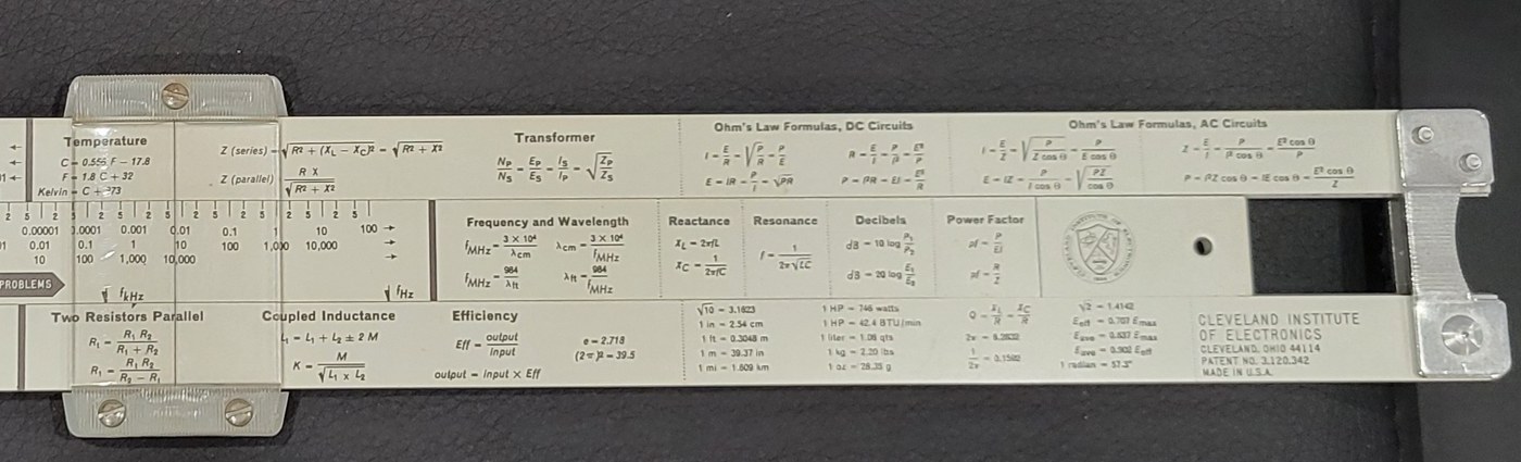
Figure 4 — The formula panels and constants on my rule, ending at the right in the CIE seal and the maker’s legend. Photo: my own.
The rest of the back face is a printed reference card. As printed on my rule, panel by panel:
Temperature
- C = 0.556 F − 17.8
- F = 1.8 C + 32
- Kelvin = C + 273
Impedance (beside the temperature panel)
- Z (series) = √(R² + (XL − XC)²) = √(R² + X²)
- Z (parallel) = RX / √(R² + X²)
Transformer
- NP/NS = EP/ES = IS/IP = √(ZP/ZS)
Ohm’s Law Formulas, DC Circuits
- I = E/R = √(P/R) = P/E
- R = E/I = P/I² = E²/P
- E = IR = P/I = √(PR)
- P = I²R = EI = E²/R
Ohm’s Law Formulas, AC Circuits
- I = E/Z = √(P / (Z cos θ)) = P / (E cos θ)
- Z = E/I = P / (I² cos θ) = E² cos θ / P
- E = IZ = P / (I cos θ) = √(PZ / cos θ)
- P = I²Z cos θ = IE cos θ = E² cos θ / Z
Frequency and Wavelength
- fMHz = 3 × 10⁴ / λcm λcm = 3 × 10⁴ / fMHz
- fMHz = 984 / λft λft = 984 / fMHz
Reactance
- XL = 2πfL
- XC = 1 / (2πfC)
Resonance
- f = 1 / (2π√(LC))
Decibels
- dB = 10 log (P₁/P₂)
- dB = 20 log (E₁/E₂)
Power Factor
- pf = P / EI
- pf = R / Z
Two Resistors Parallel
- Rt = R₁R₂ / (R₁ + R₂)
- R₁ = RtR₂ / (R₂ − Rt)
Coupled Inductance
- Lt = L₁ + L₂ ± 2M
- K = M / √(L₁ × L₂)
Efficiency
- Eff = output / input
- output = input × Eff
- e = 2.718 (2π)² = 39.5
Constants and conversions
Table 2 — Constants and conversions
| √10 = 3.1623 | 1 HP = 746 watts | Q = XL/R = XC/R | √2 = 1.4142 |
| 1 in = 2.54 cm | 1 HP = 42.4 BTU/min | 2π = 6.2832 | Eeff = 0.707 Emax |
| 1 ft = 0.3048 m | 1 liter = 1.06 qts | 1/2π = 0.1592 | Eave = 0.637 Emax |
| 1 m = 39.37 in | 1 kg = 2.20 lbs | Eave = 0.902 Eeff | |
| 1 mi = 1.609 km | 1 oz = 28.35 g | 1 radian = 57.3° |
Every constant on the card checks. A few are worth a note:
- 3 × 10⁴ and 984. The speed of light is 3 × 10¹⁰ cm/s, so f in MHz times λ in cm is 3 × 10⁴; in feet, 2.998 × 10⁸ m/s ÷ 0.3048 m/ft = 9.84 × 10⁸ ft/s, giving 984. A 7.1 MHz amateur signal therefore has λ = 984 / 7.1 = 138.6 ft, or 3 × 10⁴ / 7.1 = 4,225 cm = 42.3 m.
- The sine-wave averages. Eeff (RMS) = Emax/√2 = 0.707 Emax; the full-wave average is 2/π = 0.637 Emax; and 0.637 / 0.707 = 0.901, printed as 0.902.
- 1 HP = 42.4 BTU/min. 746 W × 60 s/min ÷ 1,055 J/BTU = 42.4.
- (2π)² = 39.5. 39.478, the constant in the resonance formula squared — useful when working f = 1/(2π√LC) the long way round.
- Two resistors in parallel. The second form, R₁ = RtR₂ / (R₂ − Rt), answers the bench technician’s question “what do I put across this resistor to get that value?” — see Volume 4.
- Coupled inductance. Lt = L₁ + L₂ ± 2M is the series total of two coils with mutual inductance M, + for series-aiding and − for series-opposing; K is the coefficient of coupling.
3.5.1 The seal and the legend
At the right-hand end of the slide is the circular CIE seal; at the right of the lower body the legend CLEVELAND INSTITUTE OF ELECTRONICS / CLEVELAND, OHIO 44114 / PATENT NO. 3,120,342 / MADE IN U.S.A. — the details used in Volume 1 to date my rule to no earlier than 1964.
The panel’s use of Hz and pF on the locator, where the 1958 patent and the 1966 manuals print cps, kc, mc and µµf, means that an owner working from the scanned manuals has to translate as he goes: cps is Hz, kc is kHz, mc is MHz, µµf (micromicrofarad) is pF. The scales themselves are unchanged.
Sources
- D. L. Geiger, Slide Rule, US Patent 3,120,342 (filed 16 October 1958, granted 4 February 1964) — the objects of the invention, the 3-4-3 subdivision, the rows of indicia and directional arrows, the 2-3-6 frequency subdivisions, the indicator marks at 0.159 and 0.318 (https://patents.google.com/patent/US3120342A/en). In this site’s Reference Library.
- D. L. Geiger, Electronics and Your Slide Rule, Part III, Cleveland Institute of Electronics, October 1966 printing — Topics 25–27 and Examples 31–34, with answers (https://www.rfcafe.com/references/electrical/Cleveland-Institute-515-T-Slide-Rule-Manuals.htm). In this site’s Reference Library: Parts I, II, III, IV.
- The formula panel and constants transcribed from my own rule (Figure 4) and cross-checked against the 1967 advertisement drawing and the RF Cafe photographs of another example.
- Every “exact” value was computed directly: f(40 mH, 0.03 µF) = 4,594 Hz; C(350 µH, 200 kHz) = 1.809 nF; XC(0.005 µF, 3 MHz) = 10.61 Ω; L(4 MΩ, 3 MHz) = 0.2122 H; f(200 pF, 25 Ω) = 31.83 MHz; f(3 mH, 175 pF) = 219.7 kHz; f(340 µH, 0.0034 µF) = 148.0 kHz; 984/7.1 = 138.6; 3 × 10⁴/7.1 = 4,225; 746 × 60/1,055 = 42.4; (2π)² = 39.48; log 2 = 0.301, log 2.5 = 0.398.
Comments (0)