Pickett N-515-T CIE Electronic · Volume 2
Pickett N-515-T Electronic (CIE) — Volume 2 — The Front Face: Electronic Scales on a Pickett Body
Eleven scales, three index marks and a red legend — what each one computes, and how the rule is built

Figure 1 — The front face of my N-515-T, end to end. Upper stator: (Lr) H, (fx) 2π, A. Slide: (Cr) B, S, T, (Lx or Cx) CI, C. Lower stator: D, L, Ln. Photo: my own.
2.1 About This Volume
Volume 1 told the story of the rule. This volume reads its front face, scale by scale. Most of it will be familiar to anyone who has used a ten-inch Mannheim-type rule: A and B for squares, C and D for multiplication, CI for reciprocals, S and T for trigonometry, L for common logarithms. What makes the face an electronics face is three things: two extra stator scales, H and 2π; a set of red labels in parentheses that rename familiar scales for circuit work — (Lx or Cx) on CI, (Cr) on B; and three index marks — XL, fr and XC — that say where a reactance or a frequency is to be read. Once those are understood, every procedure in the CIE course follows.
2.2 The Scale Set at a Glance
Reading top to bottom, with the function each scale represents in terms of x, the value on the D scale beneath the hairline (or on C, for scales on the slide):
Table 1 — Reading top to bottom, with the function each scale represents in terms of x, the value on the D scale beneath the hairline (or on C, for scales on the slide)
| Position | Scale | Red label | Function | Range | Used for |
|---|---|---|---|---|---|
| Upper stator | H | (Lr) | 1 / (2πx)² | two cycles, decreasing to the right | LC product (or L, with B) for resonance at frequency x |
| Upper stator | 2π | (fx) | x / 2π | one cycle, offset by 2π | frequency in reactance problems; dividing or multiplying by 2π |
| Upper stator | A | — | x² | 1 – 100 | squares, square roots |
| Slide | B | (Cr) | x² | 1 – 100 | squares; capacitance in resonance problems |
| Slide | S | — | sin (black), cos (red) | 5.7° – 90° | sines and cosines; impedance angles |
| Slide | T | — | tan (black), cot (red) | 5.7° – 45° | tangents and cotangents |
| Slide | CI | (Lx or Cx) | 1 / x | 10 – 1, in red | reciprocals; inductance or capacitance in reactance problems |
| Slide | C | index: XL or fr | x | 1 – 10 | multiplication and division |
| Lower stator | D | index: XC | x | 1 – 10 | the principal scale |
| Lower stator | L | — | log₁₀ x | 0 – 1.0 | common logarithms, decibels |
| Lower stator | Ln | — | ln x | 0 – 2.3 | natural logarithms, time constants |
The right-hand end of each scale carries its function in small type — x², x/2π, sin x, tan x, Log₁₀ x, Logₑ x — so the face documents itself. The scale names sit at the left-hand end, which is where the CIE manuals refer to them.
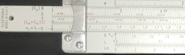
Figure 2 — The left end of my rule. The slide end is printed “ELECTRONIC MODEL N-515-T” vertically. The red legend “(Lx or Cx) CI” and the arrow “XL or fr — C” pointing down at the C index are the electronics markings; the D index below carries “XC”. Photo: my own.
2.3 The Ordinary Scales
2.3.1 C and D
C (on the slide) and D (on the lower stator) are identical single-cycle logarithmic scales from 1 to 10, ten inches long. All multiplication and division happen between them, exactly as on any slide rule (see Using Slide Rules, Vol 2). On this rule they also carry gauge marks: π (3.1416); a mark labelled hp at 7.46, the number of watts in one horsepower (746 W), so that a horsepower–watts conversion can be set without looking the figure up; and a small R at 5.73, for the 57.3 degrees in a radian.
2.3.2 A and B
A (upper stator) and B (slide) are two-cycle scales, 1 to 100, each cycle half the length of C or D. A number on D has its square directly above it on A; a number on A has its square root below it on D. The CIE course (Part II, Topics 21–23) uses them for squares, square roots and expressions containing them — Ohm’s-law power formulas such as P = I²R and E = √(PR) are the bread and butter. On the N-515-T, B has a second job in resonance problems, which its red label (Cr) — “capacitance, resonance” — signals.
2.3.3 CI
CI is C running backwards, 10 to 1, printed in red so that it is not mistaken for C. A number on C has its reciprocal directly opposite on CI. In the general course it is the reciprocal scale and the tool for chained multiplication without resetting the slide (Part II, Topics 15–18). In electronics work it carries the red label (Lx or Cx): the inductance or capacitance of a reactance problem is always set on CI.
2.3.4 S and T
Both trigonometric scales are on the slide and read against C (or D, with the slide’s indices lined up). S runs from about 5.7° to 90° and gives sines in black; the same marks carry red figures, with a ”<” sign, for the complementary angle, giving cosines. T runs from about 5.7° to 45° for tangents, with cotangents in red. In electronics these turn impedance problems into right-triangle problems: the phase angle θ of a series circuit satisfies tan θ = X/R, and Z = R / cos θ. Part IV of the course, Topics 37–43, is devoted to exactly this (“Solving Circuit Problems by Triangle Rules”).
2.3.5 L and Ln
L is the mantissa scale of common logarithms, 0 to 1.0, aligned with D: the hairline over x on D reads log₁₀ x on L. It is what turns the rule into a decibel calculator (Volume 4). Ln is a natural-logarithm scale from 0 to 2.3 — that is, from ln 1 to ln 10 — also aligned with D. The course (Part IV, Topic 44 and its appendix) introduces it as the replacement on this rule for the log-log scales of an engineering rule: it handles exponential growth and decay, the charging and discharging of a capacitor through a resistor, by giving natural logarithms directly.
Example — How long does a capacitor take to discharge from 100 V to 30 V through a resistor, when RC = 1 second? The decay is V = V₀e^(−t/RC), so t = RC · ln(100/30) = RC · ln 3.333. Set the hairline over 3.333 on D (100 ÷ 30, done first on C and D) and read 1.204 on Ln. With RC = 1 s, the answer is 1.20 seconds. (Check: ln 3.333 = 1.2040.)
2.4 The Electronic Scales
2.4.1 The 2π scale (fx)
The 2π scale on the upper stator is a copy of D displaced by the factor 2π (6.2832). With the hairline over a number on the 2π scale, 2π times that number appears under the hairline on D; with the hairline over a number on D, that number divided by 2π appears on the 2π scale. Its right-hand label reads x / 2π.
The factor 2π is everywhere in alternating-current work — angular frequency ω = 2πf, inductive reactance XL = 2πfL, capacitive reactance XC = 1/(2πfC) — so building it into the rule saves one multiplication in every reactance problem and removes a common source of slips. The course’s first two examples (Part III, Examples 35 and 36) are not electrical at all:
Example — How many degrees are there in a radian? 2π radians make 360°. Set the hairline over 360 on D and read 57.3 on the 2π scale. (360 ÷ 6.2832 = 57.296.)
Example — A generator armature turns at 1,800 rev/min, which is 30 rev/s. Its angular velocity ω = 2π × 30. Set the hairline over 30 on the 2π scale and read 188.5 on D: 188.5 radians per second. (2π × 30 = 188.50.)
Because frequency in a reactance problem is always set on this scale, it carries the red label (fx) — “frequency, reactance.”
2.4.2 The H scale (Lr)
The topmost scale, H, is the special one. It represents 1 / (2πx)², where x is the reading on D: a reciprocal, squared, two-cycle scale, with its numbers increasing from right to left. Its purpose comes from the resonance formula
f = 1 / (2π√(LC)), which rearranges to LC = 1 / (2πf)².
So with the hairline over a frequency on D, H gives the LC product that resonates at that frequency. Because the scale is squared, it covers two decades for every one of D, which is what a square root in the formula requires.
Example (Part III, Example 41) — What LC product resonates at 20 MHz? Set the hairline over 20 on D and read 633 on H. The digits alone do not say whether the answer is 6.33, 63.3 or 633 in any given units; the decimal point locator on the back (Volume 3) says it is about 70 when C is in picofarads and L in microhenrys, so the answer is 63.3 pF·µH. (Check: 1 / (2π × 2 × 10⁷)² = 6.333 × 10⁻¹⁷ s², which is 63.33 × 10⁻¹⁸ — i.e. 63.3 pF·µH.)
The red label (Lr) — “inductance, resonance” — reflects the more useful way of working: with the C index set to the frequency on D, an inductance set on H has the capacitance that resonates with it directly beneath on B (Cr), and vice versa. Volume 4 works the full procedure. The course warns that any number on H can be found in two places, giving two candidate answers on D; the decimal point locator decides which is real.
2.4.3 The three index marks
The ends of C and D carry small labels that turn the general rule into a reactance calculator:
- the C index (the 1 at the left end of C, and the 10 at the right) is marked XL or fr, with an arrow pointing down at D;
- the D index is marked XC, with an arrow pointing up at C.
The CIE course reduces every reactance problem to three rules, which are worth quoting nearly verbatim from Part III:
- Frequency is always set or read under the hairline on the 2π scale (fx).
- Inductance or capacitance is always set or read under the hairline on CI (Lx or Cx).
- Inductive reactance is always set or read on D opposite the C index (the XL mark); capacitive reactance is always set or read on C opposite the D index (the XC mark).
“In working any reactance problem set up the known values in the positions on the rule indicated by the two applicable rules above, and then read the unknown value in accordance with the remaining rule.” Why it works is straightforward. With the hairline at f on the 2π scale, D under the hairline stands at 2πf. Setting L on CI under the hairline divides that by 1/L — that is, multiplies by L — so the C index now stands over 2πfL = XL on D. With C in place of L the C index stands over 2πfC on D, and since C opposite the D index always reads the reciprocal of D opposite the C index, XC = 1/(2πfC) appears there. Volume 4 works examples of each.
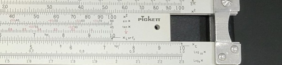
Figure 3 — The right end of my rule: the function labels (x/2π, x², sin x, tan x, Log₁₀ x, Logₑ x), the XL or fr mark at the right C index and XC at the right D index, the “hp” gauge mark near 7.46, and the block-letter PICKETT logo on the slide. Photo: my own.
2.5 How the Rule Is Built
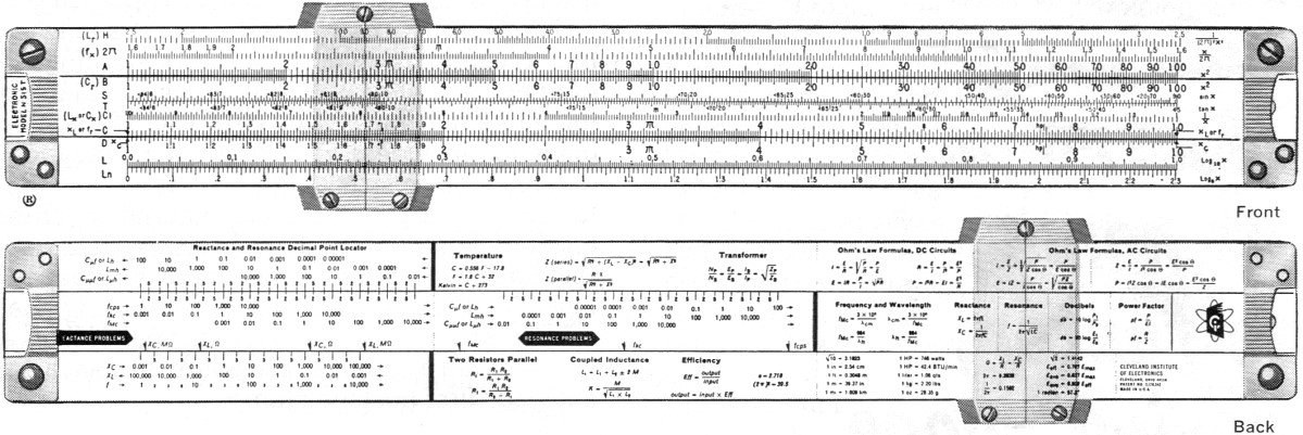
Figure 4 — The front and back faces as CIE’s advertising showed them in 1967. Note the older unit labels on the back (“fcps”, “C µµf”) compared with the Hz and pF on mine. Image: Cleveland Institute of Electronics advertisement, Electronics World, August 1967, via RF Cafe, https://www.rfcafe.com/references/electronics-world/electronics-slide-rule-august-1967-electronics-world.htm.
2.5.1 Stock, slide and end braces
The N-515-T is a standard Pickett all-aluminium duplex rule: two stator bars and a slide, all of aluminium, with ten-inch scales and an overall length of about 12⅛ inches (30.8 cm, per the Computer History Museum’s record). The bars are held together at each end by stamped aluminium end braces, each fixed with two screws. On mine the braces are the later Pickett pattern, grooved across the top and contoured to the fingertip. Pickett slides of this period run in a grooved channel with small slide-tension springs under the end braces, which keep the slide from falling out and give a slight drag.
The faces are finished in a white (off-white) paint onto which the scales are printed in black and red. That printed finish is the rule’s weak point, and governs how it may be cleaned (Volume 4): the scales sit on the surface of a paint layer, not engraved into the metal.
A hole near each end of the slide, and one through the stock, are standard Pickett features for hanging the rule or threading a lanyard.
2.5.2 The cursor
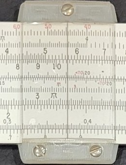
Figure 5 — The cursor on my rule: a clear plastic lens with a single hairline, carried in a frame of moulded nylon bars fixed with slotted screws (one at the top, two at the bottom on this face). Photo: my own.
The cursor is the later Pickett type: moulded nylon cursor bars carrying a clear plastic lens with a single etched or printed hairline, clamped by small slotted screws. It runs over both faces on a duplex rule, so the front hairline and the back hairline must be aligned with each other for front-to-back transfers; on the N-515-T this matters less than on an engineering duplex, because the back face is used only to locate the decimal point, to an accuracy the course itself calls “never necessary” to be high. A plastic lens scratches easily and is attacked by many solvents; see Volume 4.
2.5.3 Front and back together
The N-515-T is duplex in construction but not in the usual sense of the word. On a log-log duplex the back face is a second set of computing scales read against the same hairline. On this rule the back is a separate instrument — the coarse decimal point locator, using the same slide but its own scales — plus reference panels. The course’s method is always the same two-stage one: work the digits on the front, place the decimal point on the back. Volume 3 is about the back.
Sources
- D. L. Geiger, Electronics and Your Slide Rule, Parts II–IV, Cleveland Institute of Electronics, October 1966 printing — Part III Topics 28–29 (the 2π and H scales, Examples 35–43, the three reactance rules), Part IV (the triangle and Ln scales); scans by Joe Hernandez (KN2A) via RF Cafe (https://www.rfcafe.com/references/electrical/Cleveland-Institute-515-T-Slide-Rule-Manuals.htm). In this site’s Reference Library: Parts I, II, III, IV.
- C. Hamann, “Pickett N-515-T Radio/Electronic Slide Rule” — the front-scale functions H = 1/((2π)²x²), 2π = x/2π, B (Cr), CI (Lx or Cx), C (xL or fr), D (xC) (https://public.bht-berlin.de/hamann/sliderules/pick-cie.html).
- Computer History Museum, catalogue no. 102666658 — dimensions (https://www.computerhistory.org/collections/catalog/102666658).
- M. Konshak, Chronology of Pickett Slide Rule Development, International Slide Rule Museum — end braces, cursor bars, lenses, slide tension springs (https://www.sliderulemuseum.com/Manuals/Pickett_Chronology.pdf). In this site’s Reference Library.
- Every worked figure was checked by direct calculation: 360/2π = 57.296; 2π × 30 = 188.50; 1/(2π × 2 × 10⁷)² = 6.333 × 10⁻¹⁷; ln(100/30) = 1.2040; 746 W per horsepower.
Comments (0)