Pickett N-515-T CIE Electronic · Volume 1
Pickett N-515-T Electronic (CIE) — Volume 1 — A Slide Rule from a Correspondence School
Why a home-study electronics school in Cleveland commissioned its own slide rule, who designed it, and how to date one
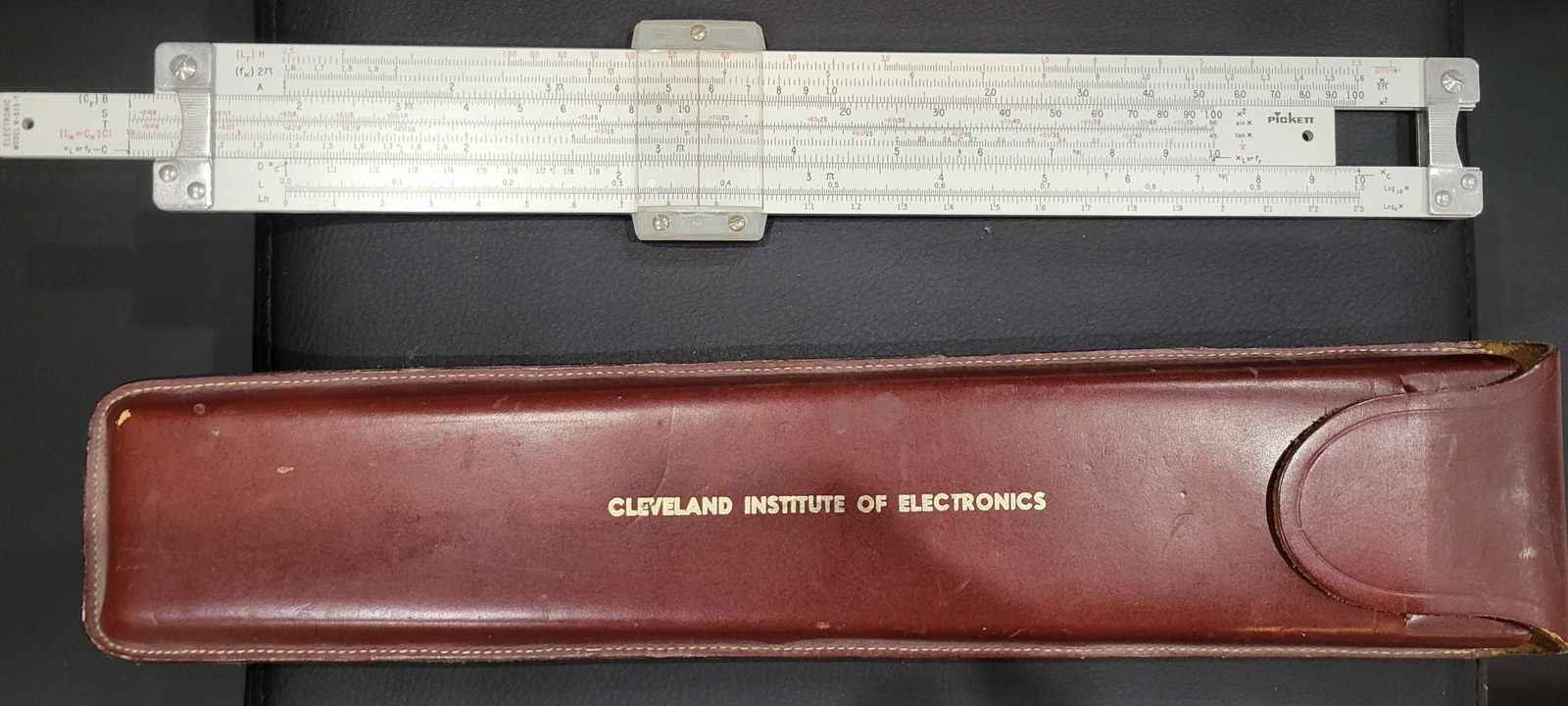
Figure 1 — My Pickett N-515-T, front face up, with its burgundy top-grain leather case stamped CLEVELAND INSTITUTE OF ELECTRONICS. The slide end reads “ELECTRONIC MODEL N-515-T”; the scale labels in red — (Lx or Cx), the H and 2π scales, the XL and XC index marks — are what set it apart from an ordinary Pickett. Photo: my own.
1.1 About This Unit
Most slide rules in a collection were bought over a shop counter. This one was not. The Pickett N-515-T was made by Pickett for exactly one customer, the Cleveland Institute of Electronics (CIE), a correspondence school that taught radio and electronics by mail, and it reached its owners as part of a home-study course. Its front face is a conventional ten-inch Pickett with three extra scales cut for radio work. Its back face is something no general-purpose rule carries: a patented Reactance and Resonance Decimal Point Locator, designed at the school by one of its own lesson writers, which tells the student where the decimal point goes in a problem that mixes microhenrys, picofarads and megahertz.
That combination — a school’s own patent, printed on a maker’s standard aluminium body, sold to students with a four-part programmed course — is what makes the N-515-T unusual enough for a unit of its own. I own one, in its CIE leather case.
1.1.1 Depth-Index: The Four-Volume Unit
Table 1 — Depth-Index: The Four-Volume Unit
| Vol | Title | Primary Content |
|---|---|---|
| 1 | A Slide Rule from a Correspondence School (this volume) | CIE and home study, why a school issued a rule, the Geiger patent, Pickett as maker, sibling school rules, dating an example |
| 2 | The Front Face: Electronic Scales on a Pickett Body | Every front scale — H, 2π, A, B, S, T, CI, C, D, L, Ln — the XL/XC/fr index marks, the cursor and the aluminium construction |
| 3 | The Back Face: The Decimal Point Locator and the Formula Panels | How Patent 3,120,342 works, reading the locator, and a full transcription of the formula and constants panels |
| 4 | Working Electronics Problems, and Caring for the Rule | Worked reactance, resonance, decibel, parallel-resistor and time-constant problems; cleaning the aluminium, the cursor and the leather case |
Note — The four CIE manuals issued with the rule, Electronics and Your Slide Rule, Parts I–IV, and the patent itself are the primary sources throughout. Where a published account disagrees with them, the disagreement is stated rather than smoothed over.
1.2 The Cleveland Institute of Electronics
1.2.1 A school by mail
The school began in 1934, when Carl E. Smith set up the Smith Practical Radio Institute in Cleveland, Ohio, to teach radio by correspondence. The name changed as the subject did: the 1958 patent application that underlies this rule was assigned to the Cleveland Institute of Radio Electronics, and by the 1960s the school traded as the Cleveland Institute of Electronics, at 1776 East 17th Street, Cleveland. Its students were mostly working adults — the advertisements address radio and television servicemen and technicians wanting to move up — who studied in the evening from printed lessons and mailed their examinations back to be graded. Enrolment is reported to have peaked at around 40,000 students in 70 countries in 1972. The school added a degree-granting subsidiary, World College, in 1992, and is reported to have closed in 2022.
Two things set CIE’s lessons apart, and both bear directly on the slide rule.
The first is the “Auto-Programmed” method, which the school trademarked and is reported to have patented in 1956. Each lesson is cut into short numbered topics, each topic ends in a “What Have You Learned?” set of practice problems with answers, and the student is expected to work every one before moving on. It is a printed form of programmed instruction: small steps, immediate feedback, no instructor in the room. The slide-rule manuals are written exactly this way.
The second is the FCC licence. A great deal of CIE’s teaching aimed at the Federal Communications Commission’s commercial radio operator licences, which a technician needed to service transmitters. The licence examinations were full of exactly the arithmetic the N-515-T was built for: reactance of a coil at a given frequency, the resonant frequency of a tuned circuit, decibel ratios, power in a load. The author of the slide-rule course, Darrell L. Geiger, also wrote Successful Preparation for FCC License Examinations for Prentice-Hall.
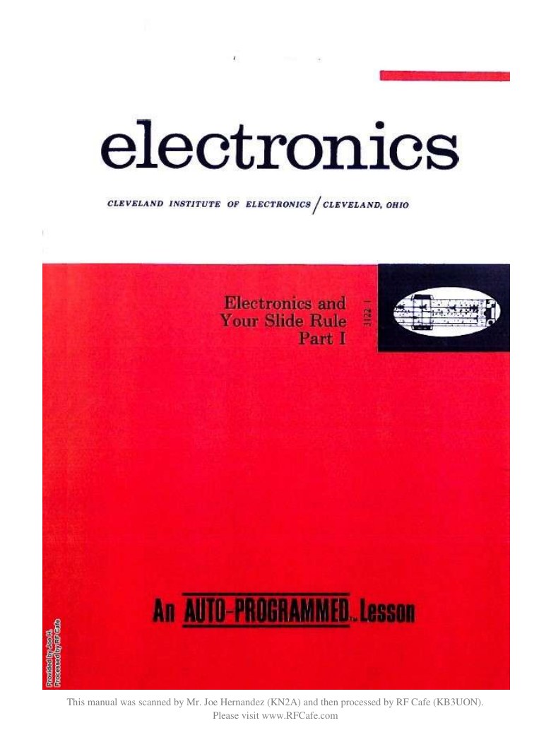
Figure 2 — The cover of Part I of the four-part CIE course that came with the rule: “electronics — Cleveland Institute of Electronics / Cleveland, Ohio — Electronics and Your Slide Rule, Part I — An AUTO-PROGRAMMED Lesson.” This is the Fourth Edition, Fifth Revised Printing of October 1966. Image: Cleveland Institute of Electronics, scanned by Joe Hernandez (KN2A), via RF Cafe, https://www.rfcafe.com/references/electrical/Cleveland-Institute-515-T-Slide-Rule-Manuals.htm.
1.2.2 Why a school issued a slide rule
An electronics technician’s arithmetic is not hard in its operations — multiply, divide, square, take a square root — but it is brutal in its magnitudes. A tuning capacitor might be 365 picofarads (3.65 × 10⁻¹⁰ farad), the coil beside it 240 microhenrys (2.4 × 10⁻⁴ henry), and the answer wanted in kilohertz. A slide rule gives the significant figures of the answer and nothing else; the operator places the decimal point by estimation or by keeping track of powers of ten. For a student working alone, with no teacher to catch a mistake, a decimal point dropped three places is the commonest way to get a perfectly reasoned problem wrong.
The patent states the problem directly: radio technicians “are frequently confronted with mathematical problems concerning the oscillation frequency of a resonant circuit” and the reactances of its parts, and such problems “heretofore could be solved by the use of a slide rule only with great difficulty and with doubtful accuracy in the result.” It sets itself two objects beyond the ordinary: to solve these problems “without need for conversion from one unit of measure to another,” and to give the decimal point location “immediately and directly.” Part III of the course says the same in a student’s terms: “Because of the rather involved formulas used for these problems and also because of the very large and very small values normally employed, locating the decimal point with certainty is a difficult task. For that reason special scales are provided on the back of your Electronics rule.”
A school-issued rule also solved a teaching problem. If every student owns the same instrument, the lessons can say “set the hairline over 0.03 on scale Cµf” and print a drawing of exactly that rule. The manuals do this on almost every page.
1.3 The Patent and Its Inventor
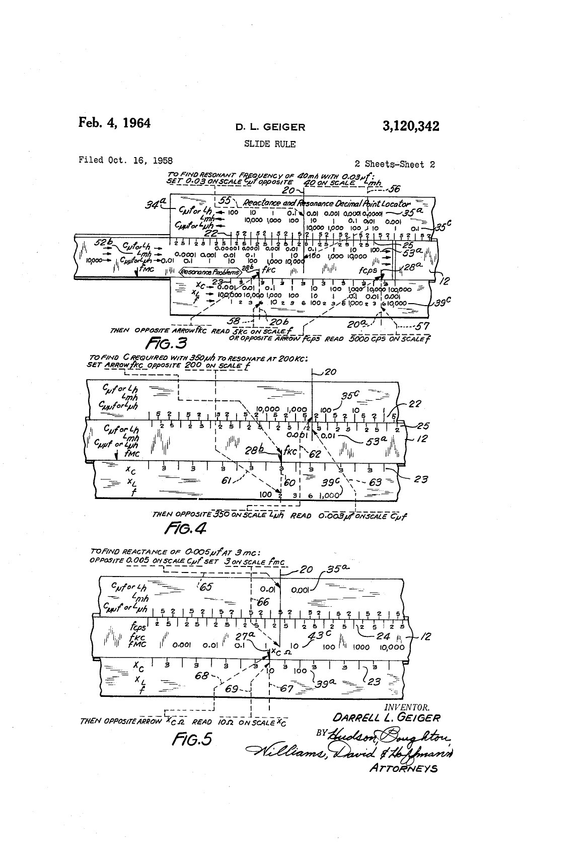
Figure 3 — Sheet 2 of the patent drawings. Fig. 3 finds the resonant frequency of 40 mH with 0.03 µF (“5 kc” or “5000 cps”); Fig. 4 finds the capacitance for 350 µH to resonate at 200 kc; Fig. 5 finds the reactance of 0.005 µF at 3 mc. The same three examples reappear in Part III of the CIE course. Image: D. L. Geiger, US Patent 3,120,342, “Slide Rule,” sheet 2, via Google Patents, https://patents.google.com/patent/US3120342A/en.
The patent number stamped on the back of the rule, 3,120,342, is a United States patent titled simply Slide Rule. It was filed on 16 October 1958 (Serial No. 767,699) and granted on 4 February 1964, with sixteen claims. The inventor is Darrell L. Geiger of Bay Village, Ohio, “assignor to Cleveland Institute of Radio Electronics, Cleveland, Ohio, a corporation of Ohio.”
Geiger was not an outside instrument designer. The “About the Author” page in each part of the CIE course describes him as the school’s Senior Project Director, with “over 15 years experience in helping students learn through home study,” who “edits much of our new lesson material.” The manuals’ title page states it outright: “ELECTRONICS SLIDE RULE NO. 515, designed by CLEVELAND INSTITUTE OF ELECTRONICS, U. S. Patent Number 3,120,342.”
Note on attribution — Chan Street of Los Angeles, the engineer behind Pickett’s own retail Electronic rules, is sometimes assumed to have designed the CIE rule too. The patent and the CIE manuals name Darrell L. Geiger and the school; no source found for this unit connects Street to the N-515-T.
What Geiger patented is the back face, not the front. The claims cover a set of coarse, decade-stepped scales whose rows of numbers are labelled directly in practical units — microfarads or henrys, millihenrys, picofarads or microhenrys; cycles, kilocycles and megacycles; ohms and megohms — together with arrow marks on the slide placed so that a reactance or a resonant frequency can be read off in the right unit without converting anything. Volume 3 takes the mechanism apart. The front face, by contrast, is essentially a standard Pickett ten-inch layout with three electronics scales added, and nothing in the patent claims it.
1.4 Pickett, the Maker
The rules themselves were made by Pickett. Roswell C. Pickett and Arthur F. Eckel went into partnership in Chicago in 1943 as Pickett & Eckel; from the early 1950s the firm’s all-aluminium rules were made in Alhambra, California, while the offices stayed in Chicago, and in 1964 the company moved to Santa Barbara and became Pickett Industries. By the time of the CIE rule, Pickett aluminium rules were among the commonest in American schools. Pickett’s aluminium construction suited a mail-order school: the 1967 CIE advertisement promises that “all-metal construction assures smooth operation regardless of climate,” a real consideration for students in the tropics and in military postings, where wooden and celluloid rules swelled and stuck.
The rule was not a Pickett catalogue model offered to the public. The CIE advertisement describes it as “made exclusively for Cleveland Institute of Electronics, to our rigid specifications, by Pickett, Inc.” The model number follows Pickett’s own system: the N prefix carried by most Pickett models of the period, 515 as the model, and the -T suffix, which the Hamann slide-rule collection reads as Pickett’s white (“traditional”) finish, as opposed to the yellow “Eye-Saver” finish marked -ES.
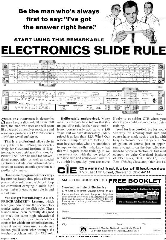
Figure 4 — CIE’s advertisement in Electronics World*, August 1967. The package — rule, top-grain leather case with “heavy-duty plastic liner” and “removable belt loop,” and four Auto-Programmed lessons — was “deliberately underpriced” at “less than $25,” as a way to recruit students: “we are looking for men in electronics who are ambitious to improve their skills… who know that this will require more training.” Image: Cleveland Institute of Electronics advertisement, Electronics World, August 1967, via RF Cafe, https://www.rfcafe.com/references/electronics-world/electronics-slide-rule-august-1967-electronics-world.htm.*
The advertisement shows how the rule worked commercially. It was sold not only to enrolled students but as a stand-alone package advertised in the electronics magazines, priced low on purpose as a recruiting tool: a technician who bought the rule and worked through the four lessons had, in effect, sampled a CIE course. The claim at the top of the copy — that the rule “solves reactance and resonance problems in 12 to 20 seconds — without pencil and paper” — is the decimal-point locator’s whole selling point.
1.5 The Four Manuals
The course issued with the rule is Electronics and Your Slide Rule, by Darrell L. Geiger, in four Auto-Programmed parts. The copyright line reads 1958, 1962, 1965 and 1966; the surviving scans are of the Fourth Edition, Fifth Revised Printing, October 1966.
Table 2 — The Four Manuals
| Part | Subtitle | Topics | Content |
|---|---|---|---|
| I | Step-by-step to Skillful Operation | 1–14 | Holding the rule, the scales, reading graduations, the decimal point, multiplication and division |
| II | Combined Operations with Electronic Applications | 15–24 | CI scale and reciprocals, chained operations, the A and B scales, squares and square roots, proportion |
| III | Combined Operations with Electronic Applications | 25–36 | The Reactance and Resonance Decimal Point Locator, reactance problems, the 2π scale, the H scale, the S and T scales |
| IV | Combined Operations with Electronic Applications | 37–44 + appendix | Solving right triangles (impedance), circuit problems by triangle rules, the L and Ln scales |
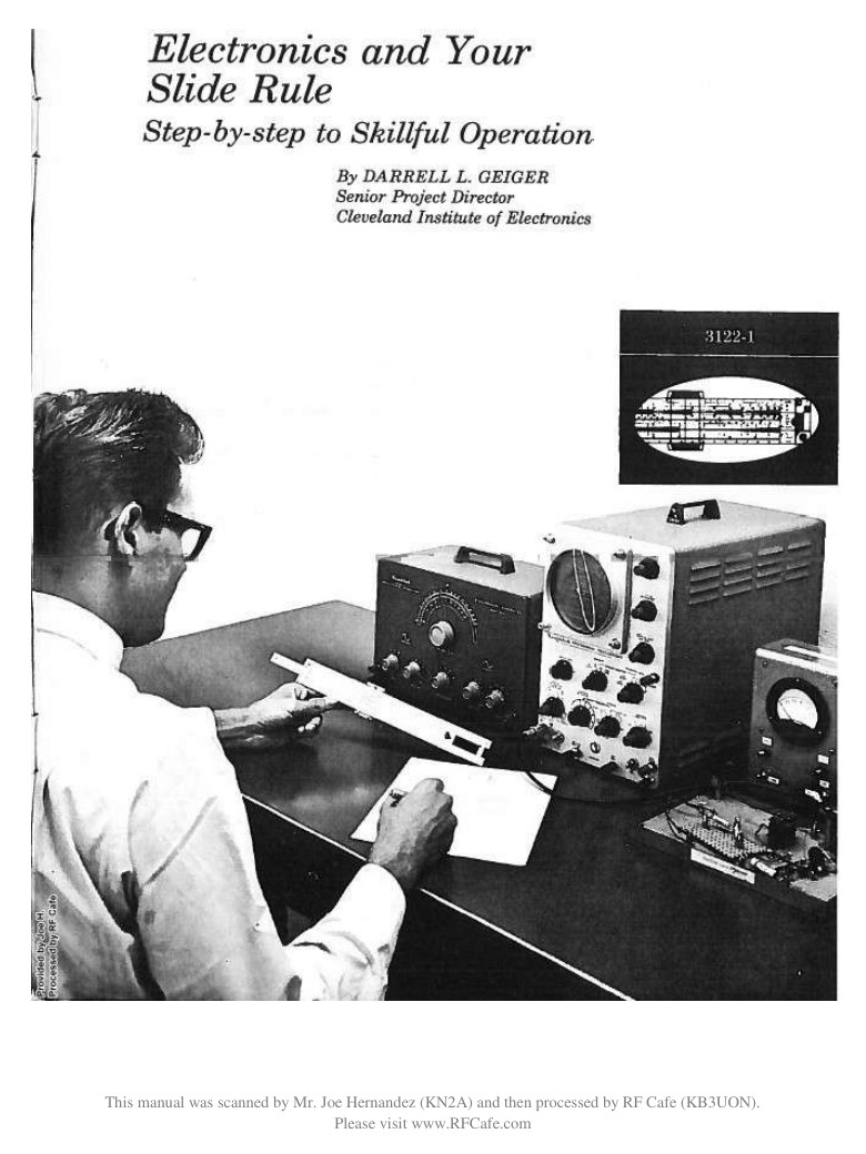
Figure 5 — The title page of Part I: “Electronics and Your Slide Rule — Step-by-step to Skillful Operation — By Darrell L. Geiger, Senior Project Director, Cleveland Institute of Electronics.” Image: Cleveland Institute of Electronics, scanned by Joe Hernandez (KN2A), via RF Cafe, https://www.rfcafe.com/references/electrical/Cleveland-Institute-515-T-Slide-Rule-Manuals.htm.
Part III is the heart of the course for anyone interested in what is special about the rule; its worked examples are reused, and checked, in Volumes 3 and 4 of this unit. All four parts are scanned and preserved in this site’s Reference Library: Parts I, II, III, IV.
1.6 Siblings: Other Electronics Rules of the Era
The N-515-T was not the only slide rule a radio school had made for it, nor Pickett’s only electronics rule.
- Pickett N-531-ES (CREI). The Capitol Radio Engineering Institute of Washington, D.C., another correspondence school, had its own Pickett: the N-531-ES, a yellow Eye-Saver duplex rule, dated by one collector’s data sheet to about 1960. Its scale set is quite different — log-log scales LL1–LL3, a DF folded scale, S, ST, T on the front; L, Ln, A, B, CI, C, D, a 2π scale and K on the back — a general engineering duplex with an electronics leaning, rather than a rule built around a decimal-point locator.
- Pickett N-16-ES Electronic. Pickett’s own retail Electronic rule, sold to the public, had electronics scales designed by Chan Street of Los Angeles. It is a full duplex rule with log-log and hyperbolic scales, aimed at engineers rather than technicians.
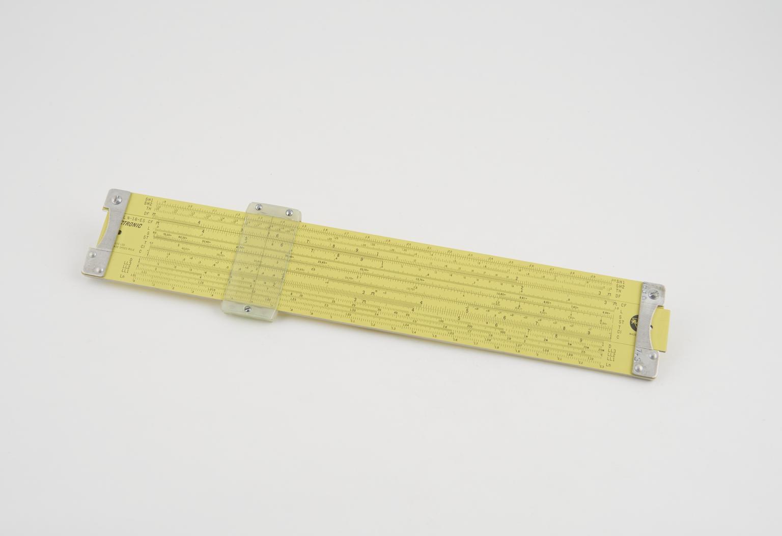
Figure 6 — For comparison: a Pickett N-16-ES Electronic, Pickett’s retail electronics rule with scales by Chan Street, in the Science Museum Group collection (object 1990-743). Its yellow Eye-Saver finish and dense duplex scale set show how far the CIE rule’s simple, single-purpose layout is from the engineer’s rule of the same maker. Image: © The Board of Trustees of the Science Museum, https://collection.sciencemuseumgroup.org.uk/objects/co61008/pickett-slide-rule.
Placed beside these, the N-515-T’s character is clear. It is a technician’s rule, not an engineer’s: no log-log scales, no hyperbolic functions, no folded scales. What it has instead is the arithmetic a working radio man met every day, laid out so that a student who had never used a slide rule could, after four lessons, get the decimal point right.
1.7 Dating and Identifying an Example
Collector sources give dates for the N-515-T from about 1958 to about 1970, which fits the course’s own copyright span (1958–1966) and the patent’s filing and grant (1958, 1964). Several features of an individual rule narrow it down.
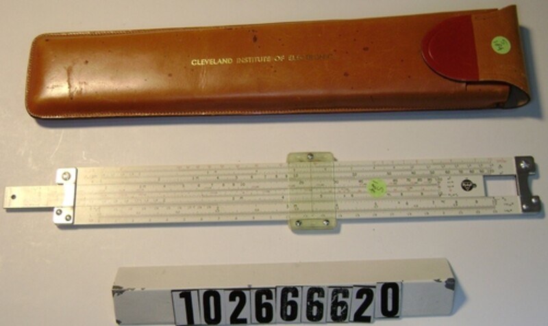
Figure 7 — An earlier N-515-T in the Computer History Museum, catalogued as made circa 1958 by Pickett & Eckel, Inc., with a lighter, orange-tan CIE case. Compare the end braces and the round Pickett logo at the right of the slide with the block “PICKETT” logo on mine. Image: Computer History Museum, catalogue no. 102666620, gift of Mike Konshak, https://www.computerhistory.org/collections/catalog/102666620.
Table 3 — Dating and Identifying an Example
| Feature | What it indicates | On mine |
|---|---|---|
| Pickett logo | The ISRM chronology of Pickett rules gives the round black logo (Style 4) to about 1958–62, the yellow circle (Style 5) to about 1962–64, and the block-letter “PICKETT” with a small triangle over the i (Style 6) to about 1964–75 | Block-letter “PICKETT” with triangle — Style 6, c. 1964 or later |
| Maker’s name | Pickett & Eckel, Inc. on early pieces; Pickett, Inc. / Pickett Industries later | Not visible in my photographs |
| End braces and cursor | Contoured, grooved stamped end braces and nylon cursor bars belong to Pickett’s later periods; grooved convex lenses to the latest | Contoured grooved braces; nylon cursor with a convex-profile lens — consistent with the late 1960s or after |
| Address on the back | ”Cleveland, Ohio 44114” uses a ZIP code, introduced in the US in July 1963 | ”CLEVELAND, OHIO 44114” — 1963 or later |
| Patent number | Printed as granted (3,120,342) only after February 1964; earlier rules could at most say “patent pending" | "PATENT NO. 3,120,342” — 1964 or later |
| Frequency and capacitance units on the locator | The 1958 patent and the 1966 manuals label the locator in cps, kc, mc and µµf (micromicrofarads); the hertz and the picofarad replaced these in American usage in the later 1960s | Mine reads fHz, fkHz, fMHz and CpF — a printing later than the 1966 manuals |
| Case | Early cases are lighter orange-tan; others a deep burgundy; some carry a Pickett logo as well as the CIE name | Burgundy top-grain leather, CIE name only on the front, D-ring belt loop on the back |
Taken together — the Style 6 logo, the ZIP code, the printed patent number and especially the Hz/pF unit labels — my rule was made no earlier than the mid-1960s and most probably in the late 1960s or the 1970s, after the manuals in the scanned set were printed. That is an inference from the features, not a dated stamp; Pickett rules of this era sometimes carry a small date code on the end of the slide or the stock, which my photographs do not show.
Sources
- D. L. Geiger, Slide Rule, US Patent 3,120,342, filed 16 October 1958, granted 4 February 1964; assigned to Cleveland Institute of Radio Electronics (https://patents.google.com/patent/US3120342A/en; PDF at https://patentimages.storage.googleapis.com/pdfs/US3120342.pdf). In this site’s Reference Library.
- D. L. Geiger, Electronics and Your Slide Rule, Parts I–IV, Cleveland Institute of Electronics, Fourth Edition, Fifth Revised Printing, October 1966; scans by Joe Hernandez (KN2A) via RF Cafe (https://www.rfcafe.com/references/electrical/Cleveland-Institute-515-T-Slide-Rule-Manuals.htm). In this site’s Reference Library: Parts I, II, III, IV.
- Cleveland Institute of Electronics, advertisement “Electronics Slide Rule,” Electronics World, August 1967, via RF Cafe (https://www.rfcafe.com/references/electronics-world/electronics-slide-rule-august-1967-electronics-world.htm).
- “Cleveland Institute of Electronics,” Wikipedia (https://en.wikipedia.org/wiki/Cleveland_Institute_of_Electronics) — founding, Auto-Programmed method, enrolment, closure. Its statement that the rule was commissioned “in the 1960s” conflicts with the 1958 patent filing and the 1958 copyright on the course; the primary documents are preferred here.
- C. Hamann, “Pickett N-515-T Radio/Electronic Slide Rule,” Hamann slide-rule pages, Berliner Hochschule für Technik (https://public.bht-berlin.de/hamann/sliderules/pick-cie.html) — scale list and the reading of the -T suffix.
- Computer History Museum, catalogue nos. 102666620 (c. 1958, Pickett & Eckel) and 102666658 (c. 1970, Pickett Industries) (https://www.computerhistory.org/collections/catalog/102666620).
- M. Konshak, Chronology of Pickett Slide Rule Development, International Slide Rule Museum, after R. Shepherd, Journal of the Oughtred Society 1:1 (1992) (https://www.sliderulemuseum.com/Manuals/Pickett_Chronology.pdf). In this site’s Reference Library.
- Following the Rules data sheets for the Pickett N-515-T (https://followingtherules.info/data-sheet-mjs-p-0174.html) and the CREI Pickett N-531-ES (https://followingtherules.info/data-sheet-mjs-p-0362.html).
- Science Museum Group, Pickett N-16-ES with electronics scales by Chan Street, object 1990-743 (https://collection.sciencemuseumgroup.org.uk/objects/co61008/pickett-slide-rule).
- Smithsonian National Museum of American History object records for Pickett rules, and B. Reichelt’s Pickett timeline in the Journal of the Oughtred Society (1999) — Pickett & Eckel’s founding, Alhambra, the 1964 move to Santa Barbara (https://si.edu/object/pickett-n600-es-log-log-duplex-slide-rule%3Anmah_694174).
- Sliderule.ca, “Pickett Slide Rules” (https://sliderule.ca/pickett.htm) — the case and the four-volume manual set.
Comments (0)