Otis King · Volume 2
Otis King's Patent Calculator — Volume 2 — Anatomy and the Scales
Holder, cylinder, cursor, two arrows, and a 66-inch helix
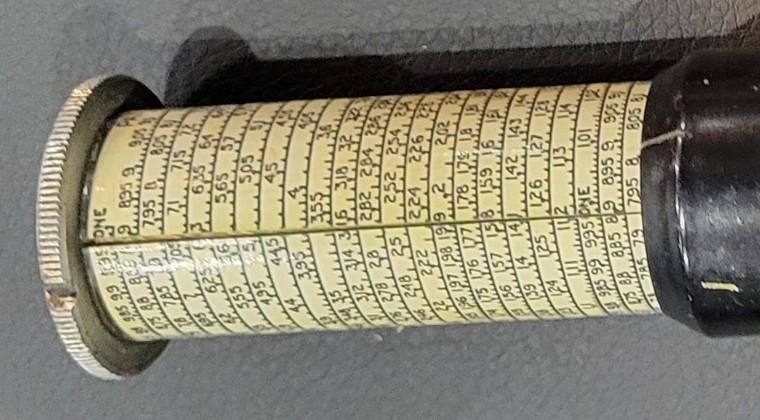
Figure 1 — The cylinder scale on mine, between the knurled knob (left) and the cursor tube (right edge). Each stripe running round the tube is one turn of the helix. “ONE” appears twice: at the knob end, and in the middle of the run, where the scale passes through unity into its second decade — the middle unity of the Model K. Photo: my own.
2.1 About This Volume
Vol 1 identified the Otis King as a model and my T3271 as a late, Type C Model K. This volume takes it apart on paper: what the three working parts are, what each scale is, how the helix is graduated, what precision it really delivers, and what it is made of. Vol 3 puts it to work and covers its care. The general geometry of a helical scale — why winding a long scale round a cylinder buys figures — is in Using a Slide Rule Vol 5 and is assumed here.
2.1.1 Depth-Index: The Otis King Unit
Table 1 — Depth-Index: The Otis King Unit
| Vol | Title | Primary Content |
|---|---|---|
| 1 | The Model | Inventor, Carbic Ltd, Models K and L, construction types, serial dating, my T3271 |
| 2 | Anatomy and the Scales (this volume) | Holder, cylinder, cursor; T and B arrows; the middle unity; K and L scales; graduation; accuracy; materials |
| 3 | Using It, and Caring for It | Worked examples; decimal point; cleaning and storage |
2.2 The Three Working Parts
The Carbic instruction leaflet describes the calculator as consisting of three parts (Carbic, Instructions, c. 1962):
- The Holder — the part held in the left hand. It ends in the chrome-plated handle, whose bottom carries the serial number, and it carries the bottom scale (the holder scale), printed on a paper strip wound helically round its tube.
- The Cylinder — the part that is drawn out of the holder. It carries the top scale (the cylinder scale) and ends in a knurled knob for turning it.
- The Cursor (or Indicator) — the black tube in the middle, which slides and turns over the junction of the other two. It carries an engraved arrow at each end: the bottom arrow, B, which points at the holder scale, and the top arrow, T, which points at the cylinder scale.
Every setting is made by moving one of two things relative to the holder — the cursor or the cylinder — and every move is a helical motion: slide along the axis to travel between turns of the helix, rotate to travel round a turn. With practice the two become a single screwing movement of the fingers.

Figure 2 — A published, labelled Model K laid out the same way as mine in Vol 1, Figure 1: knob and cylinder scale at left, black cursor tube, the start of the holder scale and the handle at right. The small white dot on the cursor near the lower arrow is the Type C “dimple” that holds the cursor together in place of screws. Image: File:Otis King Model K (horizontal).jpg by Thincat. License: CC BY-SA 3.0 (https://creativecommons.org/licenses/by-sa/3.0). Via Wikimedia Commons (https://commons.wikimedia.org/wiki/File:Otis_King_Model_K_(horizontal).jpg).

2.2.1 The arrows and the “set the arrow to the line” rule
The arrows are what make an Otis King readable. Because the cursor tube hides most of both scales, the operator never sees a C scale lying alongside a D scale as on a straight rule; there is only an arrow tip resting on a line. The instruction sheet prints its one standing order twice, in capitals, beside the outline drawing: “ALWAYS SET THE ARROWS TO THE LINES — NOT TO THE NUMBERS.” The figures are printed beside their graduations, not centred on them, and setting an arrow to the middle of a printed numeral rather than to its tick is the commonest beginner’s error. The sheet in my box carries this drawing and warning (Vol 3, Figure 1).
The two arrows are a fixed distance apart on the cursor tube. That fixed distance is the key to how the instrument computes: when the cursor moves, B travels along the holder scale exactly as far, in logarithmic terms, as T travels along the cylinder scale. Moving the cursor therefore adds (or subtracts) a logarithm read from the cylinder to one read on the holder. Vol 3 turns that into procedure.
2.3 The Scales
2.3.1 The holder scale (both models)
The holder carries a single logarithmic decade, 1 to 10, 66 inches long, wound in about 20 turns round a tube of a little over 3 inches circumference (Carbic; Lyon, OK scales). Decimal points are not marked: “the reading 212 … also serves for 2120, 21200, 21.2, 2.12, etc.” Both ends of the decade are labelled “ONE” rather than “1” and “10,” because on a logarithmic scale they are the same digit.
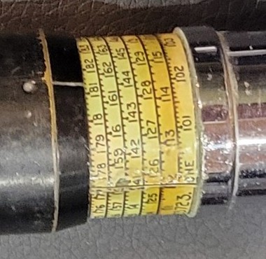
Figure 3 — The holder scale on mine where it emerges from the cursor tube. “ONE” (bottom unity) sits against the handle; each turn of the helix carries the scale up by about 12 per cent — 1.01, 1.13, 1.26, 1.42, 1.59, 1.78 on successive turns. The small pale dot on the cursor tube at left, by the bottom-arrow end, is the Type C dimple that fixes the cursor. Photo: my own.
The photographs of my instrument show the helix working as designed. Successive turns begin at about 1.01, 1.13, 1.26, 1.42, 1.59 and 1.78. Each is about 1.12 times the one before, which is what 20 turns per decade requires: 10^(1/20) = 1.122.
2.3.2 The cylinder scale: Model K
On the Model K the cylinder carries two decades in series, each “identical in all respects” with the holder scale, so the cylinder scale is twice as long — 132 inches of helix. The point where the two meet, half-way up the cylinder, is labelled “ONE” and is called the middle unity (Carbic, Instructions).
The middle unity is the Model K’s whole advantage. Whichever direction a multiplication runs, the operator can set unity to the top arrow and still have a full decade of cylinder scale on either side of it, so the cursor can always reach the second factor. A straight rule runs off its end and must be re-indexed (see Using a Slide Rule Vol 2); the Model K never does. On mine the middle “ONE” is visible in Vol 1, Figure 1 and in Figure 1 above.
2.3.3 The cylinder scale: Model L
On the Model L the cylinder carries two different scales. The upper one is a single logarithmic decade identical with the holder scale, used with it for multiplication and division. Because there is no middle unity, the “unity (one) at the top or bottom of the scale, as may be necessary, is used in its place.” The lower scale is a uniform scale from 0 to 1 in 2,000 equal divisions of 0.0005. Used against the holder scale, it reads the mantissa of the common logarithm of any number directly, and from that the leaflet derives every power and root — for example 1.008^3.1 = 1.025 and the cube root of 63 = 3.98 (both re-checked: 1.008^3.1 = 1.02501; ∛63 = 3.9791) (Carbic, Instructions).
Telling the two apart on a closed or half-open instrument comes down to that lower cylinder scale. Draw the cylinder fully out: an evenly spaced scale with figures from .000 to 1 means a Model L; logarithmic figures continuing past a mid-cylinder “ONE” mean a Model K.
2.3.4 Printed scale numbers
Each scale strip carries a small printed scale number, useful when sorting variants. Lyon records 414 / 423 (holder / cylinder) for the Model K, 429 / 430 for the Model L, and 416 / 417 on older Model L units (Lyon, Otis King’s Patent Calculator).
2.4 Graduations
The graduation interval changes along the decade so that the marks stay a readable distance apart. Lyon’s measurements of the standard scales give (Lyon, OK scales):
Table 2 — The graduation interval changes along the decade so that the marks stay a readable distance apart. Lyon's measurements of the standard scales give (Lyon, OK scales)
| Range | Graduation interval |
|---|---|
| 1 to about 1.12 | 0.001 |
| 1.12 to 2 | 0.002 |
| 2 to 4 | 0.005 |
| 4 to 10 | 0.01 |
(The Model L holder scale, 429, moves the breakpoints slightly, to 1.13, 2.0 and 3.95.) Between graduations the operator interpolates by eye, and that is where the fourth figure comes from. Near the start of the scale a setting such as 1.0645 can be made with confidence; near the top, between 9.81 and 9.82, the fourth figure is an estimate of tenths of a 0.01 interval.
2.5 How Accurate Is It?
A 66-inch decade is about eleven times the scale of a 6-inch pocket rule and nearly seven times that of a 10-inch desk rule. Since one more significant figure needs ten times the length (History Vol 4), the Otis King should read about one figure better than a desk rule. In practice it gives a reliable four significant figures, with the fifth sometimes estimable at the low end of the scale.
The finer limits are mechanical:
- Reading resolution. A setting good to about 0.01 inch (0.25 mm) on a 66-inch decade is about 0.04 per cent of the value — roughly one part in 2,500 to 6,000 depending on how well the eye does (Lyon, OK scales; Wikipedia, Otis King).
- Printing accuracy. Lyon’s scans of a Model K scale found tick-placement errors of about 0.03 per cent, and occasionally more, so a reading of 4.630 may truly be 4.632. The Model L scales he tested were more accurate (Lyon).
- Mechanical play. Any looseness between cylinder, holder and cursor tube shows up directly as a reading error, which is one reason Vol 3 is cautious about lubrication and about anything that could loosen the cursor fit.
The literature therefore quotes the Otis King at “3.5 to 4.5 digits,” depending on where on the scale and on which instrument (Using a Slide Rule Vol 5). For commercial arithmetic that was ample: a four-figure product of money or quantities checked by a final mental estimate.
2.6 Materials and Construction
- Tubes and handle. Drawn brass tubing, chrome-plated on most examples and nickel-plated on some; the earliest can be bare brass. Chrome is the bright, slightly blue mirror finish seen on my handle (Vol 1, Figure 4); nickel is warmer and duller. Plating wears through to yellow brass at the handle edge and the knob first.
- Cursor tube. Brass tube finished in black enamel on later instruments, plated or plain brass on early ones. The arrows are engraved and filled. On Type B instruments the cursor is a two-part assembly held by screws; on Type C, by a pressed dimple — the small white dot near the lower arrow.
- Scales. Printed paper strips (black on cream on the standard models; white-on-black versions exist), wound helically and glued to the tubes under a clear protective finish. The paper yellows with age and light, as the cylinder on mine has to a deeper cream than the holder strip.
- Knob and end cap. A turned, knurled cap closes the cylinder end. On Type B instruments it is usually notched to help find the ONE; mine has a small notch in the rim (Figure 4). The handle bottom carries the serial number and, on Type C, “MADE IN ENGLAND.”
- Packaging. A card box covered in black paper, lined with white card, with a printed instruction sheet folded inside. Earlier and presentation examples came in fitted, hinged cases with silk and velvet linings (Vol 1, Figure 2).
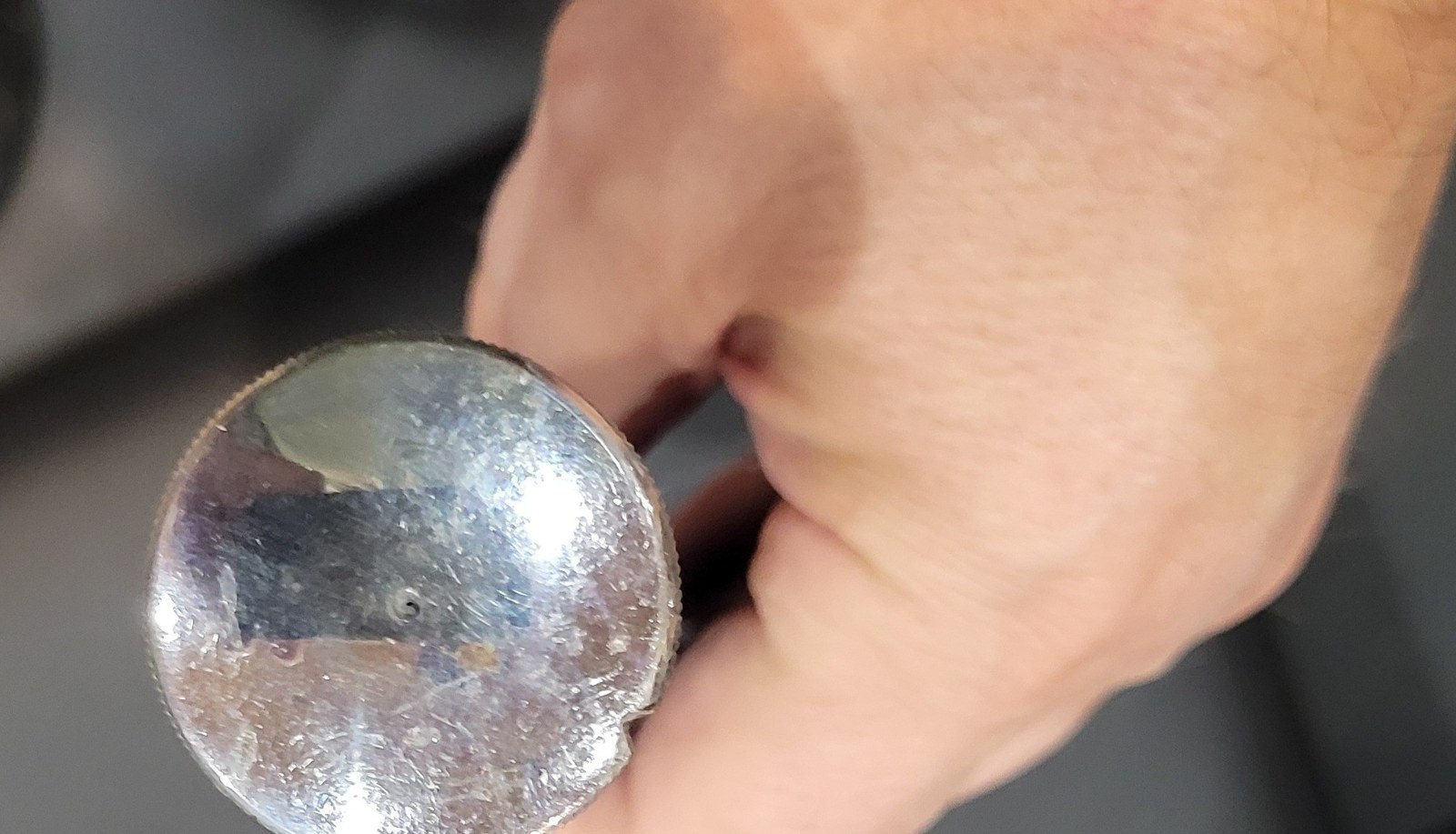
Figure 4 — The knob end of the cylinder on mine: plain, knurled round the edge, scuffed with use, with a small notch in the rim. It is unmarked; the serial and “MADE IN ENGLAND” are on the opposite end, the handle. Photo: my own.
Sources
- Carbic Ltd, Otis King’s Patent Calculator (instruction leaflet, 54 Dundonald Road, London S.W.19; c. 1962). Scan by Jaap Scherphuis (https://www.jaapsch.net/mechcalc/pdf/otisking.pdf). Parts, arrows, “set the arrows to the lines,” scale descriptions for Models K and L, Model L power/root examples. In this site’s Reference Library.
- Lyon, R. F., Otis King’s Scales and Accuracy (https://www.svpal.org/~dickel/OK/OKscales.html) and Otis King’s Patent Calculator (https://www.svpal.org/~dickel/OK/OtisKing.html). Graduation intervals, turns per decade, measured accuracy, scale numbers, cursor and plating variants.
- Scherphuis, J., Otis King’s Pocket Calculator (https://www.jaapsch.net/mechcalc/otisking.htm). Model K/L scale arrangement.
- Otis King, Wikipedia (https://en.wikipedia.org/wiki/Otis_King). 66-inch decade; one-part-in-6,000 design accuracy and observed tick errors.
Numbers checked for this volume: 10^(1/20) = 1.1220 (turn-to-turn ratio for 20 turns per decade); 66 in ÷ 6 in = 11 and 66 ÷ 10 = 6.6 (scale-length ratios); 0.01 in ÷ 66 in × log-scale conversion gives about 0.035 per cent; 1.008^3.1 = 1.02501; ∛63 = 3.97906.
Comments (0)