Fuller Cylindrical Calculator · Volume 2
Fuller's Calculator — Volume 2 — Anatomy and the Scale
A cylinder, a handle, three indexes and fifty turns of logarithms
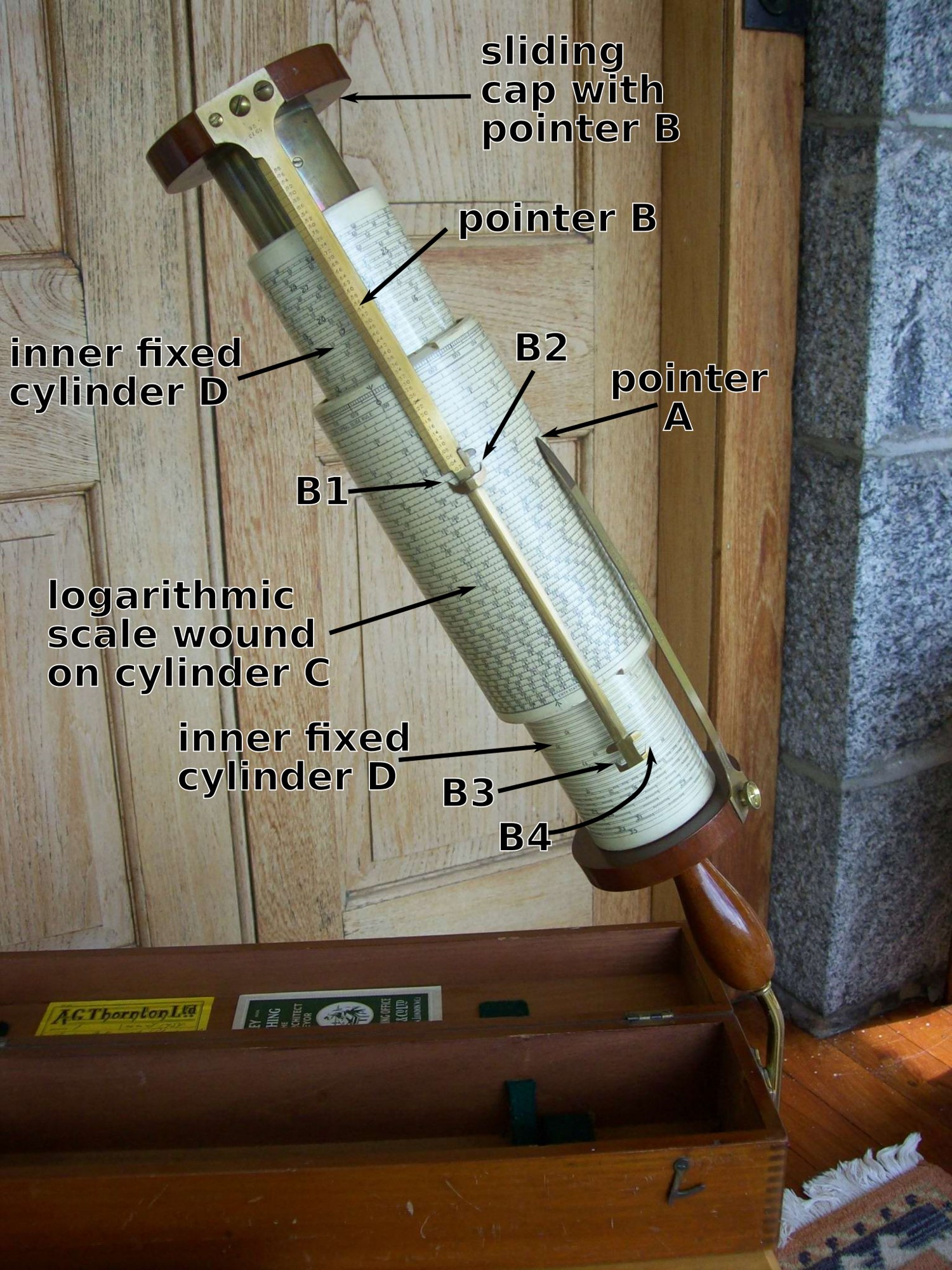
Figure 1 — The parts of a Fuller, labelled in the modern convention: the scale cylinder (C), carrying the 500-inch helix, slides and turns on the inner fixed cylinder (D) attached to the handle. Pointer A is fixed to the handle end. Pointer B hangs from a sliding cap at the top and carries index marks B1–B4. Image: File:Fuller’s calculator annotated.png by Thincat. License: CC BY-SA 4.0 (https://creativecommons.org/licenses/by-sa/4.0). Via Wikimedia Commons (https://commons.wikimedia.org/wiki/File:Fuller%27s_calculator_annotated.png).

2.1 About This Volume
Vol 1 introduced the Fuller family and how to tell its models apart. This volume describes the instrument itself: the moving parts and how they fit, the index system that makes a fifty-turn helix readable, the scale and its graduation, the linear logarithm scale that every Fuller carries, the extra scales of the No. 2 and the Fuller-Bakewell, and the materials. Vol 3 puts the instrument to work and covers its care.
2.1.1 Depth-Index: The Fuller Unit
Table 1 — Depth-Index: The Fuller Unit
| Vol | Title | Primary Content |
|---|---|---|
| 1 | The Model | George Fuller, Stanley, Models No. 1/2/3, K&E, dating, identifying mine |
| 2 | Anatomy and the Scale (this volume) | Cylinders, handle and indexes; two naming conventions; the 500-in helix; graduation and precision; the linear log scale; inner-cylinder scales; materials |
| 3 | Using It, and Caring for It | Worked examples; decimal point; adjusting the index bar; cleaning and storage |
2.2 The Parts
A Fuller has one fixed assembly and two independently moving parts.
The fixed assembly is the handle together with the inner cylinder rigidly attached to it. The handle is turned mahogany on earlier instruments and Bakelite after about 1945. The inner cylinder is a papier-mâché tube about 30 cm (12 in) long and 6.2 cm (2.4 in) in diameter. On a Model No. 1 it is printed with a table of engineering data; on the No. 2 and the Fuller-Bakewell it carries extra scales (below). A fixed index — a brass pointer — is attached to the handle end and reaches up toward the scale.
Moving part 1 — the scale cylinder. A papier-mâché tube 16.3 cm (6.4 in) long and 8.1 cm (3.2 in) in diameter, covered with the printed logarithmic scale and varnished. It slides along, and turns round, the inner cylinder. Its circumference is 8.1 cm × π = 25.4 cm, almost exactly 10 inches, so the scale’s 50 turns make up the 500-inch length.
Moving part 2 — the index bar. A long brass bar lies along the outside of the scale cylinder, carried by a cap at the top end that is mounted on a central tube (brass with a mahogany cap originally, phenolic resin from about 1935) sliding inside the inner cylinder. The bar can therefore slide and turn independently of the scale cylinder. It carries the movable indexes.
(Dimensions and materials: Wikipedia, Fuller calculator, for the 1921–35 Model 1; Stanley, Instructions, c. 1948.) The complete instrument is about 43–44 cm long and weighs about 900 g out of its box.

Figure 2 — Fuller’s own drawing of the calculator from his patent: handle, inner tube, helically ruled scale cylinder and the long index bar. Image: File:Fuller’s calculator patent drawing.jpg by George Fuller (1829–1907). License: Public domain. Via Wikimedia Commons (https://commons.wikimedia.org/wiki/File:Fuller%27s_calculator_patent_drawing.jpg).

2.2.1 Two naming conventions
The parts are named differently in Stanley’s booklet and in modern descriptions, and both appear in the sources:
Table 2 — The parts are named differently in Stanley's booklet and in modern descriptions, and both appear in the sources
| Part | Stanley booklet (c. 1948) | Modern description (Wikipedia, Figure 1) |
|---|---|---|
| Scale cylinder | cylinder D | cylinder C |
| Inner (fixed) cylinder | cylinder H | cylinder D |
| Handle | Z | handle |
| Fixed index on the handle | F | pointer A |
| Movable indexes on the bar | A (top) and B (lower), each a left/right pair | pointer B, index marks B1–B4 |
| Index reading the inner-cylinder scales | L and S | — |
This unit follows the booklet’s letters in Vol 3, because they come with the operating instructions — F for the fixed index, A and B for the movable ones — and notes the modern equivalents where a figure uses them.
2.3 The Index System
The indexes make fifty turns of scale usable. The booklet puts it plainly: the movable indexes A and B “are fixed exactly the length of the spiral scale apart. When the index A is set to the beginning of the scale, the index B should coincide with the last division on the scale” (Stanley, Instructions).
That spacing solves the problem a straight slide rule has at its ends (Using a Slide Rule Vol 2). A and B are one whole decade apart, so the readings under them always carry the same digits. Wherever the bar is set, at least one of them lies on the scale, so a setting can never fall off the end. The user simply uses whichever index is on the scale, preferring A. The fixed index F is placed so that the movable bar passes freely under it; when taking a reading, the user presses it down onto the scale with the left thumb.
Each movable index is in fact a pair, one on each side of the bar. The left pair is preferred because the graduations before the reading stay visible. Occasionally a calculation ends with F directly over the bar; it is then repeated using the right-hand pair (Stanley, Instructions).
Because the indexes are a full scale-length apart and the scale never runs out, the Fuller behaves like a straight rule twice its scale length. Hence the oft-quoted claim that it is “equivalent to a slide rule 1,000 inches (83 ft 4 in) long” (Wikipedia).
2.4 The Scale and Its Graduation
The scale is a single logarithmic decade figured 100 to 1000, wound as a 50-turn helix. Like any slide-rule scale it carries digits only; the decimal point is the operator’s business (Vol 3). Stanley’s description of the divisions (Stanley, Instructions):
Each of the primary divisions as far as 650, is divided into ten parts, and from thence to 1000 into five parts; so that all numbers of four figures have either a mark upon the scale, or are midway between two marks.
The primary divisions are the three-figure numbers 100, 101, 102 … 999. Subdividing each into ten below 650 puts a mark at every four-figure number — 4786 has its own mark. Above 650 the subdivision is into five, so marks fall on even fourth figures: 8430 and 8432 are marked, and 8431 is “midway between.” In much of the scale the subdivisions are wide enough to split by eye, giving a fifth figure. Stanley’s own example is 26854: find 268, go to the fifth subdivision (2685), and estimate the remaining 4 as about four-tenths of the next space.
How open the scale is can be checked from its length. On a 500-inch decade, the distance between two marks is 500 × log₁₀(ratio) inches:
Table 3 — How open the scale is can be checked from its length. On a 500-inch decade, the distance between two marks is 500 × log₁₀(ratio) inches
| Where | Primary division | One subdivision |
|---|---|---|
| 100 → 101 | 2.16 in | 0.216 in (5.5 mm), tenths |
| 650 → 651 | 0.334 in | 0.033 in (0.85 mm), tenths |
| 999 → 1000 | 0.217 in | 0.043 in (1.1 mm), fifths |
Even at its tightest the scale is subdivided about every millimetre, and near the start every 5½ mm, so splitting a subdivision by eye into tenths is realistic there. Stanley claimed “an accuracy of 1 in 10,000” (Stanley, Instructions). In practice the Fuller reads four significant figures always and five often, as Using a Slide Rule Vol 5 states.
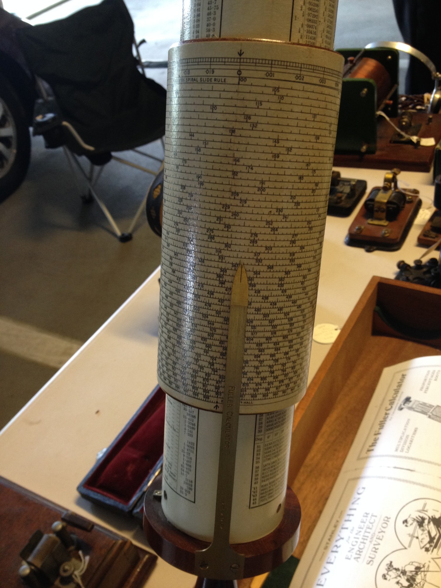
Figure 3 — The scale up close: fifty closely spaced turns, each carrying 1/50 of the decade, with the brass index bar lying along the cylinder. Image: File:Fuller Calculator closeup.agr.jpg by ArnoldReinhold. License: CC BY-SA 3.0 (https://creativecommons.org/licenses/by-sa/3.0). Via Wikimedia Commons (https://commons.wikimedia.org/wiki/File:Fuller_Calculator_closeup.agr.jpg).

2.5 The Linear Logarithm Scale
Every Fuller also carries a way of reading logarithms directly, made of two linear scales (Wikipedia; Figure 4):
- A linear scale engraved on the index bar (pointer B in the modern labels), graduated .02, .04, .06 … along the axis. Each turn of the helix is 1/50 of the decade, that is 0.02 of a logarithm, so moving one turn along the axis adds .02.
- A scale round the top circumference of the scale cylinder, divided from 0 to just under .02. It gives the fraction of a turn in finer steps.
The mantissa of the logarithm of the number under the index is the bar reading plus the circumference reading. Figure 4 shows index B1 at 1.10: the bar reads .04 and the circumference scale reads .0014, so log₁₀ 1.1 = .0414. Check: log₁₀ 1.1 = 0.04139.
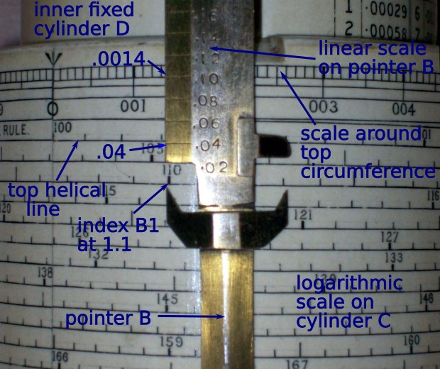
Figure 4 — Reading a logarithm: with index B1 set to 1.1 on the helix, the linear scale on the pointer gives .04 and the circumference scale .0014, so log 1.1 = .0414. Image: File:Fuller’s slide rule log calculation detail.png by Thincat. License: CC BY-SA 4.0 (https://creativecommons.org/licenses/by-sa/4.0). Via Wikimedia Commons (https://commons.wikimedia.org/wiki/File:Fuller%27s_slide_rule_log_calculation_detail.png).

2.6 The Inner-Cylinder Scales
The inner cylinder shows between the handle and the scale cylinder, and its contents identify the model (Vol 1).
Model No. 1 — table of data. No scales: printed tables of weights and strengths of materials, decimals of a foot, a degree, a hundredweight and a pound, Birmingham wire gauge, and multipliers for unit conversion (links, acres, tons, metres, gallons, horsepower). The c. 1948 booklet reproduces the tables.
Model No. 2 — logarithms and sines. Two spiral scales on the inner cylinder:
- A scale of logarithms to four decimal places, figured both ways: right-to-left readings marked + for numbers of unity or more, left-to-right readings marked − for numbers less than unity, which gives negative logarithms directly. Bring a number on the main scale to F, and its logarithm appears on the inner cylinder under the index L at the top of the scale cylinder. Stanley’s example: bring 4448 to F and read +.6481 under L, so log 4.448 = 0.6481. Check: log₁₀ 4.448 = 0.64816.
- A scale of sines from 5° 45′ to 88°, about 32 ft long, divided to single minutes up to 48° and to five minutes beyond. Bringing an angle to the index S sets F to its sine on the main scale, so triangles can be solved by ordinary multiplication and division (Vol 3).
Model No. 3, the Fuller-Bakewell — tacheometry. Two logarithmic scales either side of a zero mark just over an inch above the handle:
- cos²α, about an inch of scale below the zero, from 0° to 35°, subdivided to ten minutes up to 10° and to five minutes beyond.
- sin α · cos α, occupying most of the cylinder above the zero, from 0° 35′ to 45°, to single minutes up to 26°, then five and ten minutes.
They are read with the indexes L and S, and turn a tacheometer’s stadia intercept and vertical angle into horizontal distance and height in one setting each (Stanley, Instructions).
2.7 Materials
- Cylinders: papier-mâché tubes, covered with printed paper and shellac-varnished. Shellac gives the warm, slightly amber gloss of most surviving scales, and it governs the cleaning rules in Vol 3, because it dissolves in alcohol and blooms white with water.
- Index pointers and bar: brass, with engraved index lines and stamped serial and year. They are usually left bright or lacquered.
- Central tube: brass with a mahogany cap; phenolic resin from about 1935.
- Handle and caps: turned mahogany; Bakelite from about 1945.
- Adjusting screws: a pivot screw, a tightening screw and an eccentric cam fix the index bar to the top cap, so that the bar can be trued parallel to the axis (Vol 3).
- Box: hinged mahogany, about 46 × 12 × 11 cm, lined with fitted blocks and felt pads, with a stand fitting stored inside.
Sources
- W. F. Stanley & Co. Ltd, Instructions for the Use of the Fuller Calculator (c. 1948). Scan: University of Queensland Physics Museum (https://physicsmuseum.uq.edu.au/sites/default/files/Instructions%201948.pdf). Part letters, index spacing and pairs, graduation description and the 26854 example, inner-cylinder scales for Models No. 1, No. 2 and the Fuller-Bakewell, adjusting screws. In this site’s Reference Library.
- Fuller calculator, Wikipedia (https://en.wikipedia.org/wiki/Fuller_calculator). Dimensions and materials of the 1921–35 Model 1; materials changes c. 1935 and c. 1945; pointer A/B and B1–B4 convention; linear logarithm scales; 1,000-in equivalence.
- University of Queensland Physics Museum, Fuller’s Cylindrical Slide Rule (https://physicsmuseum.uq.edu.au/fullers-cylindrical-slide-rule-fuller-calculator).
Numbers checked for this volume: 8.1 cm × π = 25.45 cm = 10.02 in, × 50 turns ≈ 500 in; 500 in = 41 ft 8 in; graduation spacings 500 × log₁₀(101/100) = 2.161 in, 500 × log₁₀(651/650) = 0.334 in, 500 × log₁₀(1000/999) = 0.217 in; 1/50 of a decade = 0.02; log₁₀ 1.1 = 0.04139; log₁₀ 4.448 = 0.64816.
Comments (0)